Place Side Mounted Cantilever
This example shows how to place a Cantilever mounted to the side of a steel component.
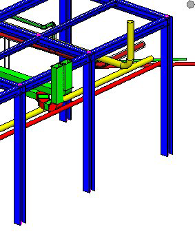
For this example, we will be working in the following location in the sample models in the Sample3 project:
- Select Cantilever or Braced Cantilever from the Support Frames menu group.
- When prompted to select pipe, select the red pipe and then accept.
- When prompted to select the structure, select the vertical beam and then accept.
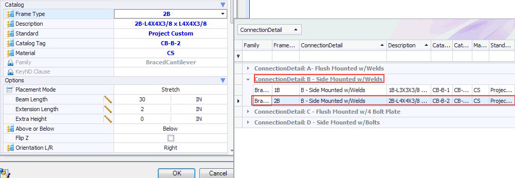
- In the property dialog, click on the Frame Type drop down.
- Drag the Connection Detail column header to top to group by connection detail, this makes it easier to select the proper cantilever.
- Because we want to connect the side of the beam, select one of cantilevers in the Side Mounted w/Welds group.
-
Set the options to define the placement:
Note: For a side mounted cantilever in stretch mode, the length of the cantilever is determined by the distance from the outer edge of the pipe to the beam plus the extension length plus the depth of the beam plus the overhang length which is define in the catalog data (in this case 2 ¼"). Also note that for the side mounted cantilevers, the orientation property determines which side of the beam that the cantilever will be placed. The side specified (left or right) is based when standing at the beam and facing the pipe.

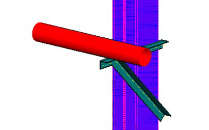
The resulting placement will display as follows:

Note: When placing the same Cantilever Support using the Input mode, the length of the beam is specified by the Beam Length Option (which is ignored when the Stretch mode is used). The Extension Length option is ignored as the Beam Length will determine the entire length. The other options (Extra Height, Above or Below, FlipZ) work the same as in the previous example.